Today i did some work on implementing the option of disabling the transmitted 150 Hz pilot tone using the Arduino Cougar Programmer.
Although you can't disable the 150 Hz. NATO RX squelch by software (this still needs to be done using the mod described in the article by Jacob PE2CJ) It is possible to disable the transmitted pilot tone using a programmer command.
A fellow OM told me this tone could be heard during a QSO so i took a look at the signal using a RTL stick and HDSDR:
150 Hz pilot tone active
Eeks !
This is the result when setting the channel's sub-tone value to 'N' in the Arduino Cougar Programmer:
In my previous posts about programming the Racal Cougar using an Arduino i described how the Racal uses the F pin of the 7-pole connector to send control data used by the programmer to the device and the commands/ protocol to do so.
This post is about the Arduino software i am writing to use it as a programmer and some of the features available.
Demo
This movie shows me using the Arduino Console to program the Racal Cougar.
The Arduino programmer
I would like the Arduino to be able to act as both a menu driven programmer
and to program the Racal Cougar with pre defined channel information by
simply connecting it to the programmer without having to connect a
computer (fill gun).
Not all features are implemented yet and there are some hurdles to take before it will be fully functional. Nevertheless, a lot has been done already and a most of the features are implemented in the Arduino already.
Menu driven programmer
Program the Racal Cougar by connecting the Arduino programmer to the computer using an USB cable and open a serial console like the one available in the Arduino IDE where commands need to be entered.
Commands
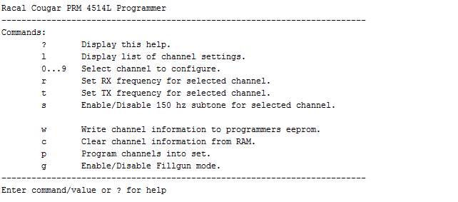
? (Question mark)
Displays information on the available commands
l (lowercase "L")
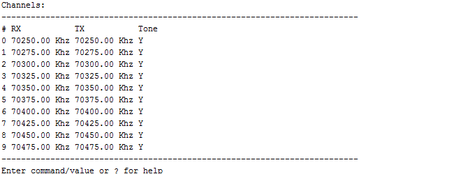
Display a list containing information about the channel frequencies currently stored in the RAM of the Arduino. This list is loaded with values stored in the Arduino's EEProm upon boot.
Channel list
0..9
To change the transmit and receive frequency for a channel one first needs to be selected. Press the channel number on the keyboard and confirm by pressing Enter to select a channel:
Channel 0 selected
r (lowercase "R")
To change the receive frequency for the selected channel press the "r" button on the keyboard and confirm by pressing Enter.
Select set receive frequency mode
After this mode is selected a frequency from 66 to 88 Mhz can be defined by entering a value in Khz, i.e. 70012.5 for 70.0125 Mhz and 70450 for 70.450 Mhz.
Receive frequency changed
t (lowercase "T")
Changing the transmit frequency for the selected channel can be done by pressing the "t" button on the keyboard and confirm using the Enter.
Selecting the transmit frequency mode
After this mode is selected a frequency from 66 to 88 Mhz can be
defined by entering a value in Khz, i.e. 70012.5 for 70.0125 Mhz and
70450 for 70.450 Mhz.
Transmit frequency changed
s (lowercase "S")
To enable or disable the 150 Hz (transmit) sub-tone for a channel.
To store the current channel frequencies defined in the Arduino to the Arduino's permanent storage, the EEProm press the "w" button and confirm by pressing Enter
Store channel info in EEProm
c (lowercase "C")
Clear the current channel settings in the Arduino's RAM by using the "c" button and confirm by pressing Enter.
Clear current channels
This command doesn't affect the channel information stored in the EEProm.
p (lowercase "P")
To program the channel settings into the Racal Cougar, press the "p" key and confirm by pressing Enter. The programmer will respond with "OK" when the program operation is successful and "Error" in case of a failure.
Successful program response
g (lowercase "G")
Enable the fill gun mode. In this mode no computer is needed to program the device, just connecting it to the 7 pole connector would be sufficient to start the program sequence.
This command isn't implemented yet.
Fill Gun mode
The fill gun mode will basically emulate the Racal fill gun (MA-4083) and would allow you to connect the Arduino to the Racal Cougar without having to connect it to the computer were after some checks the Racal will be programmed using the contents of the channel list stored in the Arduino EEProm.
This is a follow up on my firstpostabout the Racal Cougar 4 meter surplus radio and how to program this set using an Arduino. This part is about communication over the F line and the protocol used. A serious warning about hooking something up to your Racal Cougar an try to program it: do so at your own risk !
Communication
Besides connecting the microphone or MA 4730A Remote Control Unit the 7 pin connector is also used to connect the set to a device such as a programmer or fill gun.
Pinout of Audio connector
This connector has the following functions available:
Pin
Description
A
Microphone input
B
Microphone return
C
10V in or output voltage, limited to 100 mA
D
Audio out
E
Earth / 0V
F
PTT or 4k bit / sec serial data in and out
G
Squelch output
Some pins have multiple functions available which are not displayed in above table, for a complete description of the table see the technical manual available at the Crypto Museum website.
For sending and receiving commands to the set our pin of interest is the F pin. This pin has 2 functions:
PTT
Sets the transceiver in transmit mode and uses the AF signal (1mV RMS) from the microphone input (A pin) to modulate the signal.
Serial data in / out
Sets the transceiver in data mode, this mode allows an external device to communicate with the internal processor which controls the device. This communication should not be confused with packet like data where the set communicates data over the ether.
Both enabling the PTT and serial data functionality is done by putting the F pin into a low state. The difference between both modes is the duration pin low state. When the pin is kept low for 1 mS or more the ‘signal’ will be interpreted as a PTT signal otherwise it is recognized as a data signal and interrupts the processor to switch to data mode.
Serial data
Data
is send over the F line using PWM (Pulse Width Modulation). This line
its normal state is high at about 8 volt and data is send by pulling it
low for periods of time. The amount of time the line is pulled low
determines if the bit send is a 0 or a 1.
Using
a tap on pin F (PTT/Data) and E (0V) on the cable connecting the Remote
Control Unit (E.C.U) to the Racal Cougar this data can be made visible
on the oscilloscope.
Tap on the data cable
The following two screenshots are an example of the communication of the F line:
PWM serial data for switching a channel on the E.C.U.
Same data zoomed in (011111110)
When the line is pulled low for a short period of time a ‘0’ bit is send over the line and a longer low period send represents a ‘1’ bit. The zoomed in screenshot displays 9 bits from left to right with the following values: ’011111110’.
Timing
The duration of a bit send is about 240 µS. This makes the speed the data is send of the F line about 4.17 kbit/sec.
As mentioned above, the period of time the F line is pulled low determines if a ‘0’ or a ‘1’ bit is send. A short ‘pulse’ of about 64 µS is interpreted as a ‘0’ and a longer one of about 185 µS is a ‘1’.
'0' and '1' bit
Timing values of a '0' and '1' bit
Protocol
From what i have seen there are two types op data streams of bits, which i will call commands. There are 32 bit commands which tell the Racal to do something without additional data, i.e. changing to a different channel, and there are 52 bits commands which have the same pattern for the first 32 bits but have an additional 20 bits of data like a frequency to store for an selected channel.
32 and 52 bits command
The 32 bits of a command contain a header of 8 bits followed by an instruction of 8 bits and then repeat both bytes. So byte 1 and 3 are the same and so are byte 2 and 4.
Acknowledgement
For most of the commands send to the Racal it acknowledges the command is processed correctly by echoing the it back to the sending device after about 1000 to 1200 µS with bit 7 of the header (byte 1 and 3) set to '0'. This can be seen in the first screenshot of this post, there seem to be two streams of data in it where the first stream is the command being send and the second stream is the command echoed back by the set.
Programming sequence
To program the Racal Cougar PRM 4515 the following commands are send to the set (in the order they appear below and displayed in hexadecimal notation instead of bits to save me some typing :-) ): Init This is a 32 bit command without any response from the set. Lacking any knowledge about this command i called it 'init'. Programming the channels will work without this command but it seems to be required to store the channel frequencies in the EEprom instead of only the processor's RAM. Send command: 7F3B7F3B Echoed command: None Start This is also a 32 bit command but with a response from the set, i assume this is a command to tell the set there is channel frequency data incoming. Programming the channels will work without this command but it seems to
be required to store the channel frequencies in the EEprom instead of
only the processor's RAM. Send command: 7F8B7F8B Echoed command: 7D8B7D8B Channel program frequencies For every channel to be programmed two 52 bits commands are send, one command for the receive frequency and one command for the transmit frequency. These commands can be used without the other commands described. In this case the frequencies are only stored in RAM and not in the EEprom and will be reset when powering off the set.
Send command: 7EXX7EXXXXX Echoed command: 7CXX7CXXXXX Details on this command are below. Stop The same as for the start command goes here, it is a 32 bit command with an response echoed back. I haven't figured out its use yet but this command is necessary to store the changed channels in the EEprom. Send command: 7F037F03 Echoed command: 7D037D03
Channel frequency command
A command to set the frequency for a channel is made of 52 bits. there are 32 bits used for the header and instruction parts and 20 bits for the frequency information:
Header
The header used for the channel frequency command is 7E (HEX) , 01111110 (BIN). The header is repeated at byte 3.
Instruction
The 8 bits used for the instruction byte contain two pieces of information: determine if the command is used to set the RX or TX frequency and the channel number the frequency is set for.
Both parts consist of 4 bits, a nibble, where the LSB (least significant or lowest value bit) is at the left side and the MSB (most significant or highest value bit) at the right. using this method (Little Endian) The decimal value 1 is represented as 1000 instead of 0001.
TX/RX
Four bits of data to set the command for receive or transmit.A value of 1 (1000 in Little Endian notation) defines the command as being for the receive frequency and a 0 (0000) defines it as being for the transmit frequency.
Channel number
The PRM 4515(L) has 10 channels available, channel 0 to 9. Four bits in Little Endian notation define the channel number the command is set for.
Example Instruction byte for channel 7 in receive mode: 8E (HEX), 1000 1110 (BIN).
The instruction byte is repeated at byte 4.
Channel Frequency data
The last 20 bits of the Channel Frequency Command are used to define the frequency for the selected channel.
It has the following structure:
Bit 1
Parity bit for odd parity. When the number of '1' bits of the 19 following bits is even this bit will be set to 1, otherwise it will be set to 0.
Bits 2 to 4
Bits 2 to 4 store the number of times the last 0 - 87.5 Khz value of the frequency can be devided by the channel raster of 12.5 Khz. The bits are ordered in Little Endian mode which means the LSB comes first and the MSB comes last. Example: The last part of the frequency is 37.5 Khz. 37.5 divided by 12.5 is 3 which is is 011 binary. The value of bit 2 to 4 is 110 (Little Endian).
Bits 2 to 4 store information about the last 2 digits of the Khz part, at first i thought it was a Little Endian representation of the number of times the value could be divided by 12.5 Khz but this isn't corrent !
The correct values of bit 2 to 4 are based on the following table:
Khz.
Value
Hex
0
000
0
12.5
001
1
25
100
4
37.5
101
5
50
010
2
62.5
011
3
75
110
6
87.5
111
7
Bits 5 to 8
Bits 5 to 8 are used to store the 100 Khz digit. If the desired frequency is 70437.5 Khz then these bits will hold the binary representation of the value '4' which is 0100 in Little Endian notation.
Bits 9 to 12
Bits 9 to 5 are used to store the 1 Mhz digit. For a desired frequency at 70 Mhz these bits will hold the the binary representation of '0' which is 0000, When the frequency would be at 71 Mhz this value would be '1' or 1000 in binary (Little Endian).
Bits 13 to 16
Bits 13 to 16 are used to store the 10 Mhz digit. For a frequency of 70 Mhz this will be 7 which is 1110 in binary (Little Endian)
Bits 17 to 20
Although not used for the PRM 4515L (Low VHF) model of the Racal Cougar these four bits are used to store the 100 Mhz digit, for example the UHF variant, the PRM 4515U where the frequencies can be programmed within the 400 Mhz range.
Example
To set channel 7 to a receive frequency of 70.425 Mhz The following 52 bit command is used:
01111110
10001110
01111110
10001110
01000010
00001110
0000
Which would be 7E8E7E8E420E0 HEX
Whats next
I have recorded two sets of data programming the Racal Cougar using a fill gun. One with normal subtone behaviour (subtone on) and another one with the subtone turned off for every channel. I am still in the process of analyzing the commands of the subtone off fill capture and will post info about it as soon as i have done this.
The other thing is sharing a list of commands i have recorded, not only for programming the channels but also for command executed by the E.C.U. (Remote Control Unit).
In the mean time i will continue to work on the Arduino codeso it is useful for anyone who needs it.
Inspired by an article
by Jacob, PE2CJ, posted in the januari 2017 edition of the VERON (Dutch radio society) magazine about the Racal Cougar
surplus 4 meter tranceiver and how to modify the channel frequencies
stored in the EEprom i wondered if it was possible to change this
information without having to desolder the EEprom and program it outside
the set.
I ordered a set from Baco Army Goods
and after a couple of days a box containing a Racal Cougar PRM 4515L, a
10 Watt S.M.T. TA4523L/010 PA and E.C.U MA 4730A Remote control unit
arrived.
After making sure the set powered on and worked correctly the first thing i did was applying the NATO Squelch Mod described by Jacob on his website. This allowed me to do some tests with my Ascom 4 meter set which doesn't have support for a 150 hz CTCSS tone.
The plan
Programming the PRM-4515 is done using a special programmer (MA-4073) or fill gun (MA-4083). These devices are hard to find and even if you manage to find one, they will go for absurd prices.
Wouldn’t it be possible to program this set using an Arduino ?
(Technical) documentation for this set is scarce except for a technical manual for the UHF version, the PRM-4515U, hosted on the Crypto Museum website. Since the different versions of the PRM-4515 share (almost) the same processor board most of the information in this document also applies to the 4515L version.
Although there is plenty information in this manual describing how the PRM-4515(U) and its microprocessor
communicate using PWM data on the “F” pin of the audio / E.C.U connector
there is little information on the protocol used and what bits to send
to program this thing.
Reverse engineering was needed, i love it !
Reverse engineering the protocol
After making a tap on the ground (E) and PTT (F) pins and connecting
it to my oscilloscoop the PWM signal was made visible. Using the
Control Unit the data send for every command was copied in a notebook.
This gave me an overview of the data send by this unit.
Using an Arduino i was able to send these commands back to the Racal
which allowed me to change channels, crypto mode (Clear , A or B) and
Squelch On / Off.
Next i wrote a Arduino sketch that dumped the data in Hexadecimal
format on the serial console and hooked it to a fill gun, wow that's a
lot of data :-) !
There were multiple commands related to storage, sub-tone and frequencies send of which the frequency ones had my interest. Simply repeating the command is one thing but actually changing the frequency to any channel on the 12.5 kHz raster between 66 and 88 Mhz was my goal.
After looking at the data related to the frequency settings for some hours it helped a lot writing it out in binary code and after a while i noticed a pattern.
The result
Having written some Arduino test code i was able to program the channels for transmit and receive frequencies.
The movie clip shows me changing the RX frequency for channel 0. Its in dutch language and shaky and i probably need to reshoot it to be at least in English.
Next steps
Next is writing some decent code allowing you to use the Arduino
Serial Console to enter frequencies for the channels and use this to
program the Racal.
Details on the protocol, Arduino and sketch will follow !